EN 10296-2 is the primary technical standard of the European Union that defines the requirements for welded circular cross-section tubes made of stainless steel.
This document regulates the production of tubes used in mechanical engineering, construction, and for creating general-purpose metal structures. It is this standard that serves as a guarantee that the tube will withstand the declared loads and maintain corrosion resistance at the weld seams.
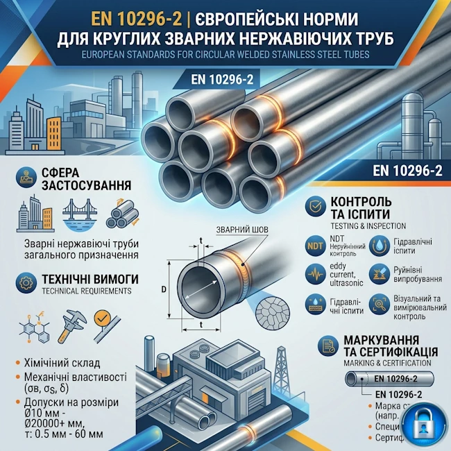
EN 10296-2 Standard: European Norms for Welded Stainless Steel Tubes
This European Standard was approved by the European Committee for Standardization (CEN) on April 4, 2005.
CEN members are bound to comply with the CEN/CENELEC Internal Regulations which stipulate the conditions for giving this European Standard the status of a national standard without any alteration. Up-to-date lists and bibliographical references concerning such national standards may be obtained on application to the Central Secretariat or to any CEN member.
This European Standard exists in three official versions (English, French, German). A version in any other language made by translation under the responsibility of a CEN member into its own language and notified to the Central Secretariat has the same status as the official versions.
CEN members are the national standards bodies of the following countries: Austria, Belgium, Cyprus, Czech Republic, Denmark, Estonia, Finland, France, Germany, Greece, Hungary, Iceland, Ireland, Italy, Latvia, Lithuania, Luxembourg, Malta, Netherlands, Norway, Poland, Portugal, Slovakia, Slovenia, Spain, Sweden, Switzerland and United Kingdom.
Ukraine and CEN
Since 2023, Ukraine has officially acquired the status of an affiliate member of CEN (European Committee for Standardization). This decision was a logical step within the framework of fulfilling the Association Agreement with the EU and the course towards "industrial visa-free regime."
What this means for the stainless steel industry:
- Harmonization without delays: Ukraine gains access to drafts of new standards during their development phase, allowing domestic manufacturers of welded tubes to adapt their facilities to new EN 10296-2 requirements in advance.
- Elimination of technical barriers: using identical regulations removes the need for additional certification or inspections when exporting tubes to EU countries.
- Recognition of DSTU EN: Ukrainian standards (DSTU EN 10296-2), which fully correspond to European ones, become a clear and reliable tool for foreign investors and developers working in Ukraine.
The status of an affiliate member of CEN confirms that the Ukrainian system of technical regulation is becoming an integral part of the single European market.
General information about the standard
| Parameter | Description |
|---|---|
| Official title | Welded circular steel tubes for mechanical and general engineering purposes. Technical delivery conditions. Part 2: Stainless steel. |
| Ratification date | September 2006 (current version of the standard). |
| Scope of application | Production of shower systems, railings, furniture fittings, medical equipment, and interior elements. |
| Product type | Circular cross-section tubes with a weld seam produced by laser or tungsten inert gas (TIG) welding. |
Table 1 — Chemical composition (cast analysis) for tubes made of ferritic, austenitic, and austenitic-ferritic corrosion-resistant steels, in % by mass
| Steel grade | C | Si | Mn | P | S | Cr | Mo | Ni | Cu | N | Nb | Ti | ||||||||
|---|---|---|---|---|---|---|---|---|---|---|---|---|---|---|---|---|---|---|---|---|
| Steel name | Steel number | max. | max. | max. | max. | max. | min. | max. | min. | max. | min. | max. | min. | max. | min. | max. | min. | max. | min. | max. |
| Ferritic steels | ||||||||||||||||||||
| X2CrNi12 | 1.4003 | 0.030 | 1.00 | 1.50 | 0.040 | 0.015 | 10.5 | 12.5 | 0.30 | 1.00 | 0.030 | |||||||||
| X2CrTi12 | 1.4512 | 0.030 | 1.00 | 1.00 | 0.040 | 0.015 | 10.5 | 12.5 | 0.030 | 6x (C+N) | 0.65 | |||||||||
| X6Cr17 | 1.4016 | 0.08 | 1.00 | 1.00 | 0.040 | 0.015a | 16.0 | 18.0 | ||||||||||||
| X3CrTi17 | 1.4510 | 0.05 | 1.00 | 1.00 | 0.040 | 0.015a | 16.0 | 18.0 | [4x(C+N)+0.15] | 0.80b | ||||||||||
| X2CrMoTi18-2 | 1.4521 | 0.025 | 1.00 | 1.00 | 0.040 | 0.015 | 17.0 | 20.0 | 1.80 | 2.50 | 0.030 | 4x(C+N)+0.15 | 0.80b | |||||||
| X6CrMoNb17-1 | 1.4526 | 0.08 | 1.00 | 1.00 | 0.040 | 0.015 | 16.0 | 18.0 | 0.80 | 1.40 | 0.040 | 7x(C+N)+0.10 | 1.00 | |||||||
| X2CrTiNb18 | 1.4509 | 0.030 | 1.00 | 1.00 | 0.040 | 0.015 | 17.5 | 18.5 | 3xC+0.30 | 1.00 | 0.10 | 0.60 | ||||||||
| Austenitic steels | ||||||||||||||||||||
| X2CrNiN18-7 | 1.4318 | 0.030 | 1.00 | 2.00 | 0.045 | 0.015 | 16.5 | 18.5 | 6.0 | 8.0 | 0.10 | 0.20 | ||||||||
| X2CrNi18-9 | 1.4307 | 0.030 | 1.00 | 2.00 | 0.045 | 0.015a | 17.5 | 19.5 | 8.0 | 10.5 | 0.11 | |||||||||
| X2CrNi19-11 | 1.4306 | 0.030 | 1.00 | 2.00 | 0.045 | 0.015a | 18.0 | 20.0 | 10.0 | 12.0 | 0.11 | |||||||||
| X2CrNiN18-10 | 1.4311 | 0.030 | 1.00 | 2.00 | 0.045 | 0.015a | 17.0 | 19.5 | 8.5 | 11.5 | 0.12 | 0.22 | ||||||||
| X5CrNi18-10 | 1.4301 | 0.07 | 1.00 | 2.00 | 0.045 | 0.015a | 17.0 | 19.5 | 8.0 | 10.5 | 0.11 | |||||||||
| X6CrNiTi18-10 | 1.4541 | 0.08 | 1.00 | 2.00 | 0.045 | 0.015 | 17.0 | 19.0 | 9.0 | 12.0 | 5xC | 0.70 | ||||||||
| X6CrNiNb18-10 | 1.4550 | 0.08 | 1.00 | 2.00 | 0.045 | 0.015 | 17.0 | 19.0 | 9.0 | 12.0 | 10xC | 1.00 | ||||||||
| X2CrNiMo17-12-2 | 1.4404 | 0.030 | 1.00 | 2.00 | 0.045 | 0.015a | 16.5 | 18.5 | 2.00 | 2.50 | 10.0 | 13.0 | 0.11 | |||||||
| X5CrNiMo17-12-2 | 1.4401 | 0.07 | 1.00 | 2.00 | 0.045 | 0.015a | 16.5 | 18.5 | 2.00 | 2.50 | 10.0 | 13.0 | 0.11 | |||||||
| X6CrNiMoTi17-12-2 | 1.4571 | 0.08 | 1.00 | 2.00 | 0.045 | 0.015 | 16.5 | 18.5 | 2.00 | 2.50 | 10.5 | 13.5 | 5xC | 0.70 | ||||||
| X2CrNiMo17-12-3 | 1.4432 | 0.030 | 1.00 | 2.00 | 0.045 | 0.015a | 16.5 | 18.5 | 2.50 | 3.00 | 10.5 | 13.0 | 0.11 | |||||||
| X2CrNiMoN17-13-3 | 1.4429 | 0.030 | 1.00 | 2.00 | 0.045 | 0.015a | 16.5 | 18.5 | 2.50 | 3.00 | 11.0 | 14.0 | 0.12 | 0.22 | ||||||
| X3CrNiMo17-13-3 | 1.4436 | 0.05 | 1.00 | 2.00 | 0.045 | 0.015a | 16.5 | 18.5 | 2.50 | 3.00 | 10.5 | 13.0 | 0.11 | |||||||
| X2CrNiMo18-14-3 | 1.4435 | 0.030 | 1.00 | 2.00 | 0.045 | 0.015a | 17.0 | 19.0 | 2.50 | 3.00 | 12.5 | 15.0 | 0.11 | |||||||
| X2CrNiMoN17-13-5 | 1.4439 | 0.030 | 1.00 | 2.00 | 0.045 | 0.015 | 16.5 | 18.5 | 4.0 | 5.0 | 12.5 | 14.5 | 0.12 | 0.22 | ||||||
| X1NiCrMoCu25-20-5 | 1.4539 | 0.020 | 0.70 | 2.00 | 0.030 | 0.010 | 19.0 | 21.0 | 4.0 | 5.0 | 24.0 | 26.0 | 1.20 | 2.00 | 0.15 | |||||
| X1CrNiMoCuN20-18-7 | 1.4547 | 0.020 | 0.70 | 1.00 | 0.030 | 0.010 | 19.5 | 20.5 | 6.0 | 7.0 | 17.5 | 18.5 | 0.50 | 1.00 | 0.18 | 0.25 | ||||
| Austenitic-ferritic steels (Duplex) | ||||||||||||||||||||
| X2CrNiN23-4c | 1.4362 | 0.030 | 1.00 | 2.00 | 0.035 | 0.015 | 22.0 | 24.0 | 0.10 | 0.60 | 3.5 | 5.5 | 0.10 | 0.60 | 0.05 | 0.20 | ||||
| X2CrNiMoN22-5-3 | 1.4462 | 0.030 | 1.00 | 2.00 | 0.035 | 0.015 | 21.0 | 23.0 | 2.50 | 3.5 | 4.5 | 6.5 | 0.10 | 0.22 | ||||||
| X2CrNiMoN25-7-4 | 1.4410 | 0.030 | 1.00 | 2.00 | 0.035 | 0.015 | 24.0 | 26.0 | 3.0 | 4.5 | 6.0 | 8.0 | 0.24 | 0.35 | ||||||
Table 2 — Permissible deviations of the product analysis from the specified limits of the cast analysis given in Table 1
| Element | Limiting values for cast analysis according to Table 1, % by mass | Permissible deviation of the product analysis, % by mass |
|---|---|---|
| C | ≤ 0.030 | + 0.005 |
| > 0.030 ≤ 0.20 | ± 0.010 | |
| Si | ≤ 1.00 | + 0.05 |
| > 1.00 ≤ 2.50 | ± 0.10 | |
| Mn | ≤ 2.00 | + 0.04 |
| P | ≤ 0.045 | + 0.005 |
| S | ≤ 0.015 | + 0.003 |
| > 0.015 ≤ 0.030 | ± 0.005 | |
| Cr | ≥ 10.5 ≤ 15.0 | ± 0.15 |
| > 15.0 ≤ 20.0 | ± 0.20 | |
| > 20.0 ≤ 26.0 | ± 0.25 | |
| Mo | > 0.80 ≤ 1.75 | ± 0.05 |
| > 1.75 ≤ 7.0 | ± 0.10 | |
| Ni | ≤ 1.00 | ± 0.03 |
| > 1.00 ≤ 10.0 | ± 0.10 | |
| > 10.0 ≤ 20.0 | ± 0.15 | |
| > 20.0 ≤ 36.0 | ± 0.20 | |
| Cu | ≤ 1.00 | ± 0.07 |
| > 1.00 ≤ 2.00 | ± 0.10 | |
| N | ≤ 0.35 | ± 0.01 |
| Nb | ≤ 1.00 | ± 0.05 |
| Ti | ≤ 0.80 | ± 0.05 |
Table 3 — Mechanical properties for tubes made of ferritic, austenitic, or austenitic-ferritic corrosion-resistant steels with thickness ≤ 30 mm
| Steel grade | Yield strength min (MPa)a | Tensile strength min (MPa)a | Elongation min (%) A | Resistance to intergranular corrosione | |||
|---|---|---|---|---|---|---|---|
| Steel name | Steel number | Rp0,2 | Rp1,0 | Rm | lb | tb | |
| Ferritic steels | |||||||
| X2CrNi12 | 1.4003 | 280 | 320 | 450 | 20 | 18 | No |
| X2CrTi12 | 1.4512 | 210 | 230 | 380 | 25 | 23 | No |
| X6Cr17 | 1.4016 | 240 | 260 | 430 | 20 | 18 | Yesc |
| X3CrTi17 | 1.4510 | 230 | 240 | 420 | 23 | 21 | Yes |
| X2CrMoTi18-2 | 1.4521 | 300 | 320 | 420 | 20 | 20 | Yes |
| X6CrMoNb17-1 | 1.4526 | 280 | 290 | 430 | 25 | 23 | Yes |
| X2CrTiNb18 | 1.4509 | 230 | 240 | 430 | 18 | 18 | Yes |
| Austenitic steels | |||||||
| X2CrNiN18-7 | 1.4318 | 330 | 370 | 630 | 45 | 45 | Yes |
| X2CrNi18-9 | 1.4307 | 190 | 225 | 470 | 40 | 35 | Yes |
| X2CrNi19-11 | 1.4306 | 180 | 215 | 460 | 40 | 35 | Yes |
| X2CrNiN18-10 | 1.4311 | 270 | 305 | 550 | 35 | 30 | Yes |
| X5CrNi18-10 | 1.4301 | 195 | 230 | 500 | 40 | 35 | Yesc |
| X6CrNiTi18-10 | 1.4541 | 200 | 235 | 500 | 35 | 30 | Yes |
| X6CrNiNb18-10 | 1.4550 | 205 | 240 | 510 | 35 | 30 | Yes |
| X2CrNiMo17-12-2 | 1.4404 | 190 | 225 | 490 | 40 | 30 | Yes |
| X5CrNiMo17-12-2 | 1.4401 | 205 | 240 | 510 | 40 | 30 | Yesc |
| X6CrNiMoTi17-12-2 | 1.4571 | 210 | 245 | 510 | 35 | 30 | Yes |
| X2CrNiMo17-12-3 | 1.4432 | 190 | 225 | 490 | 40 | 30 | Yes |
| X2CrNiMoN17-13-3 | 1.4429 | 285 | 320 | 580 | 35 | 30 | Yes |
| X3CrNiMo17-13-3 | 1.4436 | 205 | 240 | 510 | 40 | 30 | Yes |
| X2CrNiMo18-14-3 | 1.4435 | 190 | 225 | 490 | 40 | 35 | Yes |
| X2CrNiMoN17-13-5 | 1.4439 | 285 | 315 | 580 | 35 | 30 | Yes |
| X1NiCrMoCu25-20-5 | 1.4539 | 220 | 250 | 520 | 35 | 30 | Yes |
| X1CrNiMoCuN20-18-7 | 1.4547 | 300 | 340 | 650 | 35 | 30 | Yes |
| Austenitic-ferritic steels (Duplex) | |||||||
| X2CrNiN23-4d | 1.4362 | 400 | - | 600 | 20 | - | Yes |
| X2CrNiMoN22-5-3 | 1.4462 | 450 | - | 700 | 20 | - | Yes |
| X2CrNiMoN25-7-4 | 1.4410 | 550 | - | 800 | 15 | - | Yes |
Table 4 — Mechanical properties of tubes made of austenitic heat-resisting steels in the solution annealed condition (+AT)
| Steel grade | Yield strength min (MPa)a | Tensile strength min (MPa)a | Elongation min (%) A | |||
|---|---|---|---|---|---|---|
| Steel name | Steel number | Rp0,2 | Rp1,0 | Rm | lb | tb |
| X15CrNiSi20-12 | 1.4828 | 230 | 270 | 550 | 30 | 30 |
| X9CrNiSiNCe21-11-2 | 1.4835 | 310 | 350 | 650 | 40 | 40 |
| X12CrNi23-13 | 1.4833 | 210 | 250 | 500 | 35 | 35 |
| X8CrNi25-21 | 1.4845 | 210 | 250 | 500 | 35 | 35 |
| X6CrNiSiNCe19-10 | 1.4818 | 290 | 330 | 600 | 40 | 40 |
| X6NiCrSiNCe35-25c | 1.4854 | 300 | 340 | 650 | 40 | 40 |
Appearance
Tubes shall be free from external and internal surface defects that can be detected by visual examination.
The internal and external surface finish of the tubes shall be typical of the manufacturing process and, where applicable, the heat treatment used. The finish and surface condition shall allow the identification of any surface imperfections requiring rectification.
The removal of surface imperfections is permitted only by grinding or machining, provided that the wall thickness in the dressed area is not less than the specified minimum wall thickness. All dressed areas shall blend smoothly into the contour of the tube.
Surface imperfections that exceed the minimum wall thickness are considered defects, and tubes containing them shall be deemed non-compliant with this standard.
For tubes with an outside diameter D ≥ 114.3 mm, repair of the weld seam is permitted provided that a compatible filler metal is used. Such weld repairs shall not exceed 20% of the seam length. Repair welding must be performed according to a written Welding Procedure Specification (WPS).
The repaired tube must meet all the requirements of this document.
Integrity
For tubes supplied with specific inspection, the weld seam shall be subjected to non-destructive testing.
Non-destructive testing of the weld seam over the entire length of each tube is performed according to established procedures.
Tubes supplied with specific inspection shall be subjected to a leak test.
The leak test for each tube is conducted according to technical regulations.
Straightness
For tubes with an outside diameter of 33.7 mm or greater, the deviation from straightness over any length L shall not exceed 0.0020 L.
By special requirement, the deviation from straightness may be limited to 0.0015 L.
For tubes of smaller diameter, the requirements and measurement methods are agreed upon at the time of ordering.
End Preparation
Tubes shall be supplied with ends cut nominally square to the axis of the tube and shall be free from excessive burrs.
Dimensions, Masses, and Tolerances
Outside Diameter and Wall Thickness
Dimensions shall comply with EN ISO 1127, and the mass calculation is based on density according to EN 10088-1.
Lengths
The standard delivery length is 6,000 mm.
By agreement, tubes may be supplied in random or exact lengths.
Tolerances on Diameter and Out-of-Roundness
The tolerance on outside diameter (including out-of-roundness) is:
- For D ≤ 168.3 mm: ± 0.75% or ± 0.3 mm (whichever is greater).
- For D > 168.3 mm: ± 1.0%.
Tolerances on Wall Thickness (T)
The tolerance on wall thickness is ± 10% or ± 0.2 mm (whichever is greater), unless otherwise agreed.
Tolerances
Special Diameter Tolerances
By special requirement, tubes with a specified outside diameter D ≤ 114.3 mm shall be supplied with a tolerance, including out-of-roundness, of ± 0.5% or ± 0.15 mm (whichever is greater).
Wall Thickness
The tolerance on wall thickness, excluding the weld zone, shall be ± 10% or ± 0.2 mm (whichever is greater).
Weld Seam Height
The external weld bead of tubes manufactured by high-frequency (HF) welding must be completely removed flush with the outside surface of the tube.
Table 5 — Maximum weld seam height (in millimeters)
| Weld finish | Maximum weld seam height for wall thickness (T) | |
|---|---|---|
| T ≤ 8 | T > 8 | |
| Execution A | (0.20) T + 0.5 | T / 3 |
| Execution B (for D ≤ 114.3 mm) | (0.05) T + 0.3 | — |
| Execution B (for D > 114.3 mm) | (0.05) T + 0.5 | T / 6 |
| Execution C | 0.15 | — |
Table 6 — Length tolerances (in millimeters)
| Length type | Length (L) | Tolerance |
|---|---|---|
| Standard | 6,000 | +100 / 0 |
| Random | Length range by agreement | |
| Exact | ≤ 6,000 | +5 / 0 |
| 6,000 < L ≤ 12,000 | +10 / 0 | |
| > 12,000 | + / - by agreement | |
Sectional Properties
Nominal sectional properties shall be calculated in accordance with Annex C.
Inspection and Testing
Types of Inspection and Testing
Compliance with the requirements of the order for tubes manufactured according to this document shall be verified by:
- Non-specific inspection and testing (according to EN 10021);
- By special requirement — specific inspection and testing.
Inspection Documents
Document Types
The following inspection documents shall be issued in accordance with EN 10204:
- For tubes with non-specific inspection — declaration of compliance with the order or, if requested, a test report;
- For tubes with specific inspection — inspection certificate or, if requested, a certificate.
When requesting a certificate, the purchaser shall inform the manufacturer of the name and address of the organization or person appointed to carry out the inspection, and agree on the party issuing the document.
Content of Inspection Documents
The content of the documents shall comply with EN 10168. Documents shall contain the following codes and information:
For declaration of compliance:
- A — Commercial transactions and parties involved;
- B — Description of products to which the document applies;
- Z — Confirmation of compliance.
For test report:
- A — Commercial transactions and parties involved;
- B — Description of products;
- C02 — Direction of test pieces preparation.
Additionally for specific inspection certificates:
- C10-C13 — Tensile test;
- C50-C59 — Bend test;
- C71-C92 — Chemical composition;
- D01 — Marking, appearance, and dimensions;
- D02-D99 — Other non-destructive tests;
- Z — Validation.
Table 7 — Inspection and Testing Requirements
The testing requirements are given in the table below:
| Type of Inspection or Test | Non-specific Inspection | Specific Inspection | |
|---|---|---|---|
| Mandatory Tests | |||
| Cast analysis | Manufacturer's procedure | 1 per cast | |
| Tensile test | Manufacturer's procedure | 1 per test unit | |
| Flattening testa | Manufacturer's procedure | 1 per test unit | |
| Dimensional inspection and visual examination | According to regulation | ||
| Material identification | Individual | Individual | |
| Additional Tests (by agreement) | |||
| Leak tightness test | Not applicable | Individual | |
| Non-destructive testing of the weld | Not applicable | Individual | |
a The choice between the flattening, drift expanding, or bend test is at the manufacturer's discretion.
Sampling
Frequency of Testing
Test Unit:
In the case of specific inspection, the test unit shall consist of tubes of the same specified diameter and wall thickness, the same steel grade, the same cast, and the same manufacturing process route.
Table 8 — Test Unit
| Outside Diameter D (mm) | Maximum number of tubes per test unit |
|---|---|
| D ≤ 114.3 | 400 |
| 114.3 < D ≤ 323.9 | 200 |
| D > 323.9 | 100 |
* Calculated based on a maximum tube length of 20 m.
Preparation of Samples and Test Pieces
Number of Samples
One sample tube shall be taken from each selected test unit.
General Preparation Requirements
Samples and test pieces shall be taken from the tube ends in accordance with the requirements of EN ISO 377.
Test Pieces for Tensile Test
Preparation of test pieces is carried out according to EN 10002-1:
- For D ≤ 219.1 mm: the test piece shall be either a full section of the tube or a longitudinal strip.
- For D > 219.1 mm: a machined round cross-section test piece from a non-flattened part is used, or a strip in the longitudinal or transverse direction (at the manufacturer's discretion).
Important: In all cases, the test piece shall be taken from a position diametrically opposite to the weld seam.
Test Pieces for Technological Tests
- Flattening or Drift Expanding: test piece consists of a full tube section (EN ISO 8492 or 8493).
- Bend: full tube section test piece according to EN ISO 8491.
- Ring Tensile: full tube section according to EN ISO 8496.
- Weld Bend: preparation according to EN 910.
Test Methods
Tensile Test
The test is carried out at room temperature according to EN 10002-1 to determine the following indicators:
- Tensile strength (Rm);
- Proof strength (Rp0.2) and, where applicable, (Rp1.0);
- Elongation after fracture (A) on a gauge length of 5.65√S0.
Flattening Test
Carried out according to EN ISO 8492. The weld shall be positioned at 90° to the direction of flattening.
The tube section is flattened until the distance between the platens reaches 67% of the nominal outside diameter. After the test, the specimen shall show no cracks or flaws.
Drift Expanding Test
Carried out according to EN ISO 8493. A conical mandrel with an angle of 30° is used.
Table 9 — Drift Expansion Requirements
Parameters for increasing the outside diameter in the drift expanding test:
| Ratio d/D* | Increase in outside diameter (%) |
|---|---|
| ≥ 0.8 | 17 |
| < 0.8 and > 0.6 | 15 |
| ≤ 0.6 | 9 |
* Note: The ratio is calculated as d = D - 2T, where D is the specified outside diameter and T is the specified wall thickness.
Bend and Ring Tensile Tests
Bend (Full Section): Carried out according to EN ISO 8491. The bend angle is 180°, and the radius is 6 times the outside diameter of the tube.
Ring Tensile: Carried out according to EN ISO 8496 for tubes with an outside diameter D > 150 mm.
Weld Bend Test
Tests shall be carried out according to EN 910 on tubes with a specified outside diameter D > 150 mm using a mandrel diameter of 6T.
One test shall be a root bend test and the other a face bend test.
After testing, the specimen shall not show any cracks or flaws. However, imperfections less than 3 mm long on the edges of the test piece shall not be considered a cause for rejection.
Leak Tightness Test
General Provisions
ERW and laser-welded tubes shall undergo leak testing accordingly. The choice of method remains at the manufacturer's discretion unless an option is specified as the purchaser's choice.
Submerged arc-welded tubes shall be tested accordingly.
Electromagnetic Test
The test shall be carried out in accordance with EN 10246-2.
Hydrostatic Test
Carried out at a pressure of 70 bar or at pressure P (whichever is lower):
- P — pressure (bar); D — diameter (mm); T — wall thickness (mm);
- S — stress (MPa), corresponding to 70% of the min. yield strength.
Note: Holding time: 5s (D ≤ 457 mm) or 10s (D > 457 mm). This is a leak test, not a strength test.
Dimensional Inspection
Outside diameter is measured with a gauge (for D ≥ 168.3 mm — with a tape). Wall thickness is measured at a distance of no more than 100 mm from the ends.
Inspection and Identification
Visual Examination: Checking for the absence of surface defects.
NDT of the Weld: Under Option 5, performed according to EN 10246 standards (levels U4, E3, or R2).
Identification: Verifying the steel grade for each tube.
Retests
Sorting and reprocessing are carried out in accordance with the requirements of EN 10021.
Marking
General Requirements
Marking shall be durable and include: manufacturer's brand, dimensions, steel grade, cast number, and delivery condition symbol (+AR, etc.).
For specific inspection, the inspector's mark and order identification number are added.
Marking Example:
X - 48.3 x 3.6 - EN 10296-2 - 1.4301 - C - Y - Z
| X | — manufacturer's name or trademark |
| C | — cast number or code number |
| Y | — inspection representative's mark |
| Z | — identification number (order/item number) |
Bundles
For tubes in bundles, the marking may be applied to a securely attached label.
Handling and Packaging
Tubes shall be protected from contact with carbon steel strapping (which shall not touch the surface of the stainless tube).
Additional protection measures for storage and delivery are agreed upon during ordering.
Annex A — Manufacturing Process Route and Surface Condition
| Symbol | Manufacturing Route | Surface Condition |
|---|---|---|
| W0 | Welded from hot or cold rolled plate, sheet or strip (1D, 2D, 2E, 2B) | As-welded |
| W1 | Welded from hot rolled plate, sheet or strip (1D), descaled | Metallically clean |
| W1A | Welded from hot rolled plate, sheet or strip (1D), heat treated, descaled | Metallically clean |
| W1R | Condition W1 + heat treated in a controlled atmosphere | Metallically bright |
| W2 | Welded from cold rolled plate, sheet or strip (2D, 2E, 2B), descaled | Metallically clean |
| W2A | Welded from cold rolled plate, sheet or strip (2D, 2E, 2B), heat treated, descaled | Substantially smoother than W1 and W1A |
| W2R | Welded from cold rolled plate, sheet or strip (2D, 2E, 2B), bright heat treated | Metallically bright |
| WCA | Welded from hot or cold rolled plate or strip, cold formed (min. 20%), heat treated, descaled | Metallically clean, weld seam barely visible |
| WCR | Same as WCA, but with bright heat treatment | Metallically bright, weld seam barely visible |
| WG | Ground | Metallically bright-ground; roughness grade as agreed |
| WP | Polished | Metallically bright-polished; roughness grade as agreed |
Annex B — Guidelines for Heat and Hot Processing
| Table B.1 — Guidelines for ferritic corrosion-resisting steels | |||||
|---|---|---|---|---|---|
| Steel grade | Heat treatment | Hot processing | |||
| Name | Number | Annealing temperature, °C | Type of coolinga | Temperature, °C | Type of cooling |
| X2CrNi12 | 1.4003 | 700 – 750 | water, air or gas | 1100 – 800 | air or gas |
| X2CrTi12 | 1.4512 | 750 – 850 | water, air or gas | 1100 – 800 | air or gas |
| X6Cr17 | 1.4016 | 750 – 850 | water, air or gas | 1100 – 800 | air or gas |
| X3CrTi17 | 1.4510 | 750 – 850 | water, air or gas | 1100 – 800 | air or gas |
| X2CrMoTi18-2 | 1.4521 | 820 – 880 | water, air or gas | 1100 – 800 | air or gas |
| X6CrMoNb17-1 | 1.4526 | 820 – 880 | water, air or gas | 1100 – 800 | air or gas |
| X2CrTiNb18 | 1.4509 | 870 – 930 | water, air or gas | 1100 – 800 | air or gas |
| Table B.2 — Guidelines for austenitic and austenitic-ferritic steels | |||||
|---|---|---|---|---|---|
| Steel grade | Heat treatment (annealing) | Hot processing (bending) | |||
| Name | Number | Temperaturea, °C | Type of coolingb | Temperature, °C | Type of cooling |
| Austenitic steels | |||||
| X2CrNiN18-7 | 1.4318 | 1020 – 1100 | water, air or gas | 1150 – 850 | air or gas |
| X2CrNi18-9 | 1.4307 | 1000 – 1100 | water, air or gas | 1150 – 850 | air or gas |
| X5CrNi18-10 | 1.4301 | 1000 – 1100 | water, air or gas | 1150 – 750 | air or gas |
| X6CrNiTi18-10 | 1.4541 | 1000 – 1100 | water, air or gas | 1150 – 850 | air or gas |
| X2CrNiMo17-12-2 | 1.4404 | 1030 – 1110 | water, air or gas | 1150 – 850 | air or gas |
| X6CrNiMoTi17-12-2 | 1.4571 | 1030 – 1110 | water, air or gas | 1150 – 850 | air or gas |
| Austenitic-ferritic steels (Duplex) | |||||
| X2CrNiN23-4 | 1.4362 | 950 – 1050 | water, air or gas | 1150 – 950 | air or gas |
| X2CrNiMoN22-5-3 | 1.4462 | 1020 – 1100 | water, air or gas | 1150 – 950 | air or gas |
| X2CrNiMoN25-7-4 | 1.4410 | 1040 – 1120 | water, air or gas | 1150 – 1000 | air or gas |
b Cooling should be sufficiently fast to avoid carbide precipitation.
| Table B.3 — Guidelines for austenitic heat-resisting steels | |||||
|---|---|---|---|---|---|
| Steel grade | Heat treatment | Hot processing | |||
| Name | Number | Temperature, °C | Type of coolinga | Temperature, °C | Type of cooling |
| X15CrNiSi20-12 | 1.4828 | 1050 – 1150 | water, air or gas | 1150 – 850 | air or gas |
| X12CrNi23-13 | 1.4833 | 1050 – 1150 | water, air or gas | 1150 – 850 | air or gas |
| X8CrNi25-21 | 1.4845 | 1050 – 1150 | water, air or gas | 1150 – 850 | air or gas |
| X6CrNiSiNCe19-10 | 1.4818 | 1020 – 1120 | water, air or gas | 1100 – 850 | air or gas |
| X10NiCrSiNb35-25 | 1.4854 | 1100 – 1150 | water, air or gas | 1150 – 850 | air or gas |
Annex C — Formulas for Calculating Nominal Sectional Properties
| Geometric Property | Symbol | Calculation Formula | Units |
|---|---|---|---|
| Specified outside diameter | D | — | mm |
| Specified wall thickness | T | — | mm |
| Calculated inside diameter | d | d = D - 2T | mm |
| Surface area per unit length | As | As = πD / 103 | m2/m |
| Cross-sectional area | A | A = π(D2 - d2) / (4 · 102) | cm2 |
| Mass per unit length | M | M = ρA | kg/m |
| Second moment of area (Moment of inertia) | I | I = π(D4 - d4) / (64 · 104) | cm4 |
| Radius of gyration | i | i = √(I / A) | cm |
| Elastic section modulus | Wel | Wel = 2I · 10 / D | cm3 |
| Plastic section modulus | Wpl | Wpl = (D3 - d3) / (6 · 103) | cm3 |
| Torsional inertia constant (Polar moment) | It | It = 2I | cm4 |
| Torsional modulus constant | Ct | Ct = 2Wel | cm3 |