When choosing a stainless steel hollow section for load-bearing structures, the key factor is not only the steel grade but also the precision of its manufacturing. The EN 10219-2 standard is a European technical regulation that establishes strict requirements for tolerances, dimensions, and static properties of sections.
EN 10219-2 Standard: Geometry and Precision
Using pipes that comply with this standard guarantees:
Scope of Application and Technical Limits
The EN 10219-2 standard establishes limit deviations for cold-formed welded sections of circular, square, and rectangular shapes with a wall thickness up to 40 mm. Technical standards cover the following ranges:
Symbols and Definitions
Table 1 — Symbols and Definitions according to EN 10219-2
| Symbol | Unit | Definition |
|---|---|---|
| A | cm² | Cross-sectional area. |
| As | m²/m | External surface area per unit length. |
| B | mm | Specified side dimension of a square hollow section. Specified dimension of the shorter side of a rectangular hollow section. |
| C1 / C2 | mm | Length of the corner region of a square or rectangular hollow section. |
| Ct | cm³ | Torsional section modulus constant. |
| D | mm | Specified outside diameter of a circular hollow section. |
| Dmax / Dmin | mm | Maximum and minimum outside diameter of a circular hollow section measured in the same plane. |
| e | mm | Deviation from straightness. |
| H | mm | Specified dimension of the longer side of a rectangular hollow section. |
| I | cm⁴ | Second moment of area (moment of inertia). |
| It | cm⁴ | Torsional inertia constant (polar moment of inertia only in the case of circular hollow sections). |
| i | cm | Radius of gyration. |
| L | mm | Length. |
| M | kg/m | Mass per unit length. |
| O | % | Out-of-roundness (ovality). |
| R | mm | External corner radius of a square or rectangular hollow section. |
| T | mm | Specified wall thickness. |
| V | mm | Total measured twist. |
| V1 | mm | Twist measured at one end of the section. |
| Wel | cm³ | Elastic section modulus. |
| Wpl | cm³ | Plastic section modulus. |
| x1 | mm | Concavity of a side of a square or rectangular hollow section. |
| x2 | mm | Convexity of a side of a square or rectangular hollow section. |
| yy | — | Axis of the cross-section, major axis of a rectangular hollow section. |
| zz | — | Axis of the cross-section, minor axis of a rectangular hollow section. |
| θ | ° | Angle between adjacent sides of a square or rectangular hollow section. |
Information to be Obtained by the Manufacturer
The following mandatory information according to this part of EN 10219 shall be provided to the manufacturer at the time of enquiry and order:
- Type of length, length range or specific length (see Table 4 of the standard);
- Dimensions (according to Section 8 of the standard).
Note: This information complements the requirements of the EN 10219-1 standard.
Tolerances on Dimensions, Shape and Mass
General: Deviations in dimensions and shape shall not exceed the values given in Table 2 (shape and mass), Table 3 (external corner profiles), Table 4 (length) and Table 5 (weld bead height for S.A.W. pipes).
Internal corners: The internal corners of square and rectangular sections shall be rounded. Note: the specific radius or profile of the internal corner is not regulated.
Additional tolerances: For pipes with diameter D ≥ 900 mm or with a D/T ratio ≥ 50, additional tolerances for out-of-roundness, accidental eccentricity and dents may be agreed upon.
Table 2 — Tolerances on Shape and Mass according to EN 10219-2
| Characteristic | Circular Hollow Sections | Square and Rectangular Hollow Sections | ||||||||
|---|---|---|---|---|---|---|---|---|---|---|
| Outside dimensions (D, B, H) | ± 1% with a minimum of ± 0.5 mm and a maximum of ± 10 mm |
| ||||||||
| Wall thickness (T) | For D ≤ 406.4 mm: - T ≤ 5 mm: ± 10% - T > 5 mm: ± 0.5 mm For D > 406.4 mm: - ± 10% with a maximum of ± 2 mm | T ≤ 5 mm: ± 10% T > 5 mm: ± 0.5 mm | ||||||||
| Out-of-roundness (O) | 2% for hollow sections with a diameter to thickness ratio not exceeding 100a | — | ||||||||
| Concavity / Convexity (x₁, x₂)b | — | Max. 0.8% with a minimum of 0.5 mm | ||||||||
| Squareness of sides (θ) | — | 90° ± 1° | ||||||||
| External corner profile (C₁, C₂ or R) | — | See Table 3 | ||||||||
| Twist (V) | — | 2 mm plus 0.5 mm/m length | ||||||||
| Straightness (e) | 0.20% of total length and 3 mm over any 1 m length | 0.15% of total length and 3 mm over any 1 m length | ||||||||
| Mass per unit length (M) | ± 6% on individual delivered lengths | |||||||||
Table 3 — Tolerances on external corner profile (EN 10219-2)
| Wall thickness, T (mm) | External corner profile, C₁, C₂ or Ra (mm) |
|---|---|
| T ≤ 6 | 1.6T to 2.4T |
| 6 < T ≤ 10 | 2.0T to 3.0T |
| 10 < T | 2.4T to 3.6T |
Table 4 — Tolerances on delivery lengths
| Type of lengtha | Length range or length L (mm) | Tolerance |
|---|---|---|
| Random length | 4 000 ≤ L ≤ 16 000 with a range of 2 000 per order item | 10% of the sections supplied may be below the minimum of the ordered range, but not shorter than 75% of the minimum range length |
| Approximate length | ≥ 4 000 | ± 50 mm |
| Exact lengthb | < 6 000 | +5 0 mm |
| 6 000 ≤ L ≤ 10 000 | +15 0 mm | |
| L > 10 000 | +5 0 mm + 1 mm/m |
Table 5 — Tolerance on height of internal and external weld bead
| Thickness, T (mm) | Maximum weld bead height (mm) |
|---|---|
| ≤ 14.2 | 3.5 |
| > 14.2 | 4.8 |
Measurement of Dimensions and Shape
General
All external dimensions, including out-of-roundness, shall be measured at a distance from the end of the hollow section of not less than D for circular sections, B for square sections or H for rectangular sections, with a minimum of 100 mm.
Outside Dimensions
For circular hollow sections, the diameter (D) shall be measured either directly (e.g. with a calliper) or by circumference tape at the discretion of the manufacturer.
The limiting positions for measuring B and H for square and rectangular hollow sections are shown in Figure 1.
Wall Thickness
The wall thickness (T) shall be measured at a position not less than 2T from the weld.
The limiting positions for measuring the thickness of square and rectangular hollow sections are shown in Figure 1.

Figure 2 — Measurement of concavity and convexity of square or rectangular sections
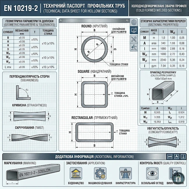
Out-of-roundness
The out-of-roundness (O) of a circular hollow section shall be calculated using the following formula (for piling pipes see Annex A):
Concavity and Convexity
The concavity (x1) or convexity (x2) of the sides of a square or rectangular hollow section shall be measured as shown in Figure 2.
The percentage concavity or convexity shall be calculated as follows:
(x1 / H) × 100%; (x2 / H) × 100%
where B and H are the side dimensions containing the concavity x1 or convexity x2.

Diagram of general cross-sectional geometry deviations

Diagram for measuring x₁ and x₂ deviations
Squareness of Sides
The deviation from squareness of a square or rectangular hollow section shall be measured as the difference between 90° and the angle θ, as shown in Figure 3.
"The deviation from squareness of the sides of a square or rectangular hollow section shall be measured as the difference between 90° and the angle θ, as shown in Figure 3."

Figure 3 — Measurement of angle θ
External Corner Profile
The external corner profile is measured by one of two methods at the manufacturer's discretion: using a radius gauge or by measuring the distances C₁ and C₂.
"The distance between the intersection point of the flat side and the corner arc and the intersection point of the projections of the flat sides at the corner shall be measured (C₁ and C₂ in Figure 4)."

Figure 4 — External corner profile
Twist
The twist of a section is determined by measuring the deviation of one of the corners from a horizontal plane while the opposite end of the pipe is fixed rigidly to a surface.
"At the opposite end of the hollow section, the difference in height of the two bottom corners from the horizontal surface shall be determined (see Figure 5)."

Figure 5 — Section twist
Method of Measuring Twist
For accurate determination of the twist value, the standard provides for the use of a spirit level and a micrometer screw. The measurement is carried out at both ends of the section.
"Twist V is the difference between V1 values measured at each end of the hollow section. The reference length for the level shall be the distance between the intersection points of the flat sides and the corner arcs (see Figure 6)."
Key for Figure 6:
- 1 — Spirit level
- 2 — Distance H for rectangular or B for square sections
- V1 — Deviation value measured by micrometer

Figure 6 — Twist measurement
Straightness
Deviation from straightness (e) over the entire length of the section is measured at the point of greatest departure from a straight line connecting its two ends.
Percentage deviation calculation formula:
(e / L) × 100% where L — actual length of the section
Local deviation: in addition to the total value, the local deviation (e1) from straightness on any 1-metre length (L1) shall not exceed 3 mm.

Figure 7 — Measurement of deviation from straightness
Dimensions and Sectional Properties
The nominal sectional properties of hollow sections complying with the requirements of the EN 10219 standard and manufactured within the specified tolerances are calculated in accordance with Annex B for the purposes of structural design.
Standard property values for a limited range of cold-formed section sizes are provided in the following tables:
All sectional properties specified in the tables are calculated using the formulas contained in Annex B.
Note: Not all dimensions and wall thicknesses specified in Tables C.1, C.2, and C.3 are available from every individual manufacturer. Users are recommended to check the availability of specific sizes. Additionally, other sizes and thicknesses may be available within the scope of this standard.
Annex A (informative)
Special Requirements for Pipes Used as Bearing Piles
A.1 General
This annex provides recommendations for additional tolerances that may be applied to pipes when used as bearing piles or primary elements in combined walls. These requirements generally apply to pipes with a diameter ≥ 900 mm and a diameter to wall thickness ratio D/T > 100.
The design of tubular piles subjected to shell buckling should be guided by the relevant pile design provisions. Shell buckling is partly determined by its geometric imperfections caused by out-of-roundness, accidental eccentricity, and indentations (dents). Limits for each of these imperfections are established based on the chosen fabrication quality class. Detailed information on how to assess out-of-roundness, accidental eccentricity, and indentations, as well as recommended maximum allowable values for each fabrication quality class, are provided in sections A.2, A.3, and A.4.
NOTE 1: Additional information on fabrication quality classes, their significance for design, and definitions of symbols can be found in the relevant regulatory documentation.
NOTE 2: Values for certain parameters given in Tables A.1, A.2, and A.3 may be subject to change at the national level. Nationally determined parameters are provided in the relevant national annexes to the design standards.
A.2 Out-of-roundness Tolerance
The out-of-roundness of a tubular pile is assessed by parameter U — the difference between the maximum and minimum values of the measured internal diameter relative to the nominal internal diameter (see Figure A.1), determined by the formula:
Where:
- — dmax — maximum measured internal diameter;
- — dmin — minimum measured internal diameter;
- — dnom — nominal internal diameter (d = D - 2T, see B.2).
To determine the maximum and minimum values, an appropriate number of diameters should be measured.
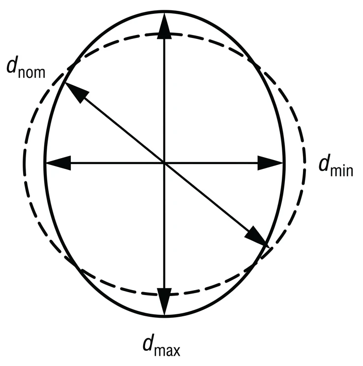
Figure A.1 — Assessment of dmin and dmax and relation to d
The out-of-roundness parameter U shall satisfy the condition:
where:
- — Ur, max — maximum allowable value of the out-of-roundness parameter.
Recommended values for each fabrication quality class are given in Table A.1.
Table A.1 — Maximum allowable values for the out-of-roundness parameter Ur, max
| Fabrication quality class | Description | Diameter range (d), mm | ||
|---|---|---|---|---|
| d ≤ 500 | 500 < d < 1250 | 1250 ≤ d | ||
| Value Ur, max a | ||||
| Class A | Excellent | 0.14 | 0.007 + 0.0093 (1.25 - d) | 0.007 |
| Class B | High | 0.02 | 0.010 + 0.0133 (1.25 - d) | 0.01 |
| Class C | Normal | 0.03 | 0.015 + 0.020 (1.25 - d) | 0.015 |
a Values for this parameter may be changed according to national annexes to design standards. In case of doubt, the relevant National Annex should be consulted.
Additional Delivery Conditions
Any special tolerances required for pile driving or on-site assembly welding are optional. They apply only if previously agreed between the customer and the supplier at the time of ordering.
A.3 Accidental Eccentricity Tolerance
Accidental eccentricity (unintentional eccentricity due to misalignment of pipe walls in horizontal joints) is assessed using the parameter Ue, which is determined by the formula:
Where:
- — ea — accidental eccentricity between the mid-points of the pipe walls at the joint;
- — T — nominal wall thickness of the pipe.
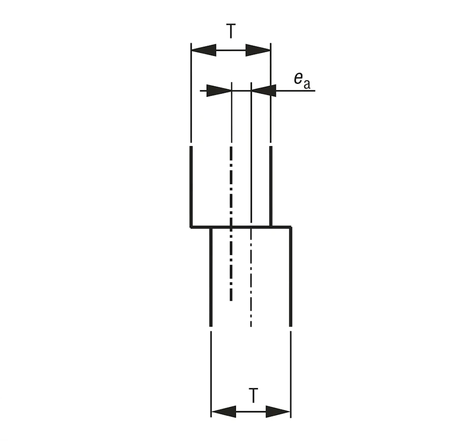
Figure A.2 — Measurement of pipe wall eccentricity (ea)
The accidental eccentricity ea and parameter Ue shall satisfy the following conditions:
Recommended maximum values for each fabrication quality class are given in the table below.
Table A.2 — Maximum allowable values for the accidental eccentricity parameter Ue, max and eccentricity ea, max
| Fabrication quality class | Description | Ue, max a | ea, max a |
|---|---|---|---|
| Class A | Excellent | 0.14 | 2 |
| Class B | High | 0.2 | 3 |
| Class C | Normal | 0.3 | 4 |
Note: Dimensions in mm.
a Values for these parameters may be changed according to national annexes to design standards. In case of doubt, the relevant National Annex should be consulted.
A.4 Tolerance for dents (local imperfections)
The depth of initial dents in the pipe wall w0 is measured in both the meridional (longitudinal) and circumferential directions using a gauge of length lg. The gauge length is determined as follows:
- a) In the meridional and circumferential directions: lg = 4 * √(r * T)
- b) Across weld beads: lg = 25 * T, but not exceeding 500 mm
The gauge for meridional measurements shall be straight. For circumferential measurements, a gauge with a radius of curvature r is used, where:
The level of initial dents in the pile wall is assessed using the tolerance parameter Ud:
Figure A.3 — Measurement of dent depth (w0)
The dent tolerance parameter Ud shall satisfy the following condition:
Recommended maximum values for each quality class are given in the table below:
Table A.3 — Maximum allowable values for the dent tolerance parameter Ud, max
| Fabrication quality class | Description | Ud, max a |
|---|---|---|
| Class A | Excellent | 0.006 |
| Class B | High | 0.01 |
| Class C | Normal | 0.016 |
NOTE: dimensions in mm. For joints involving pipes of different thicknesses, it is recommended to refer to the relevant standard.
a Values for this parameter may be changed according to national annexes to the standard.
Annex B (normative)
Formulas for the Calculation of Sectional Properties
B.1 General
Tables C.1, C.2, and C.3 of this standard provide nominal sectional properties for a limited range of cold-formed hollow section sizes. The nominal sectional properties for sections supplied to the requirements of this standard shall be calculated using the formulas given below.
NOTE: The designation of the major axis of the section (yy) and its minor axis (zz) are consistent with the axis designations used for structural design in the Structural Eurocodes. This is a change from previous axis designations.
B.2 Circular Hollow Sections
Sectional properties for circular hollow sections, as given in Table C.1, are calculated using the formulas presented below.
Table B.1 — Sectional properties for circular hollow sections
| Property | Calculation formula | Unit |
|---|---|---|
| External surface area (As) | (π × D) / 103 | m²/m |
| Cross-sectional area (A) | π × (D2 - d2) / (4 × 10²) | cm² |
| Mass per unit length (M) | 0.785 × A | kg/m |
| Second moment of area (I) | π × (D4 - d4) / (64 × 104) | cm⁴ |
| Radius of gyration (i) | √(I / A) | cm |
| Elastic section modulus (Wel) | (2 × I × 10) / D | cm³ |
| Plastic section modulus (Wpl) | (D3 - d3) / (6 × 10³) | cm³ |
B.3 Rectangular and Square Hollow Sections
The properties for rectangular and square sections (Tables C.2 and C.3) are calculated according to the EN 10219-2 methodology:
Table B.2 — Sectional properties for rectangular and square hollow sections
| Parameter / Property | Calculation formula | Unit |
|---|---|---|
| Geometry and Areas | ||
| External radius (ro) | 2.0T (T≤6) | 2.5T (6<T≤10) | 3.0T (T>10) | mm |
| Surface area (As) | As = (2/103) × (H + B - 4ro + πro) | m²/m |
| Cross-sectional area (A) | A = [2T(H+B-2T)-(4-π)(ro2-ri2)] / 102 | cm² |
| Mechanics and Torsion | ||
| Second moment of area (Iyy) | Iyy = [(BH3-(B-2T)(H-2T)3)/12 - 4(Ig+Aghg2) + 4(Iξ+Aξhξ2)] / 104 | cm⁴ |
| Torsional inertia constant (It) | It = [T3 × (h/3) + 2KAh] / 104 | cm⁴ |
| Torsional section modulus (Ct) | Ct = 10 × [It / (T + K/T)] | cm³ |
Subsidiary calculation values:
• Ig = 0.00359 × ro4
• Rc = (ro + ri) / 2
• Ah = (B-T)(H-T) - 0.8584 × Rc2
• K = 2AhT / h
* Sectional properties are calculated on the basis of nominal dimensions of the section taking into account corner radii.